
Haha, slowly it goes… Changing the SKR v1.4 to a SKR MINI V3 isn’t straight forward on the Biqu B1.


Haha, slowly it goes… Changing the SKR v1.4 to a SKR MINI V3 isn’t straight forward on the Biqu B1.


Here comes the fun part.
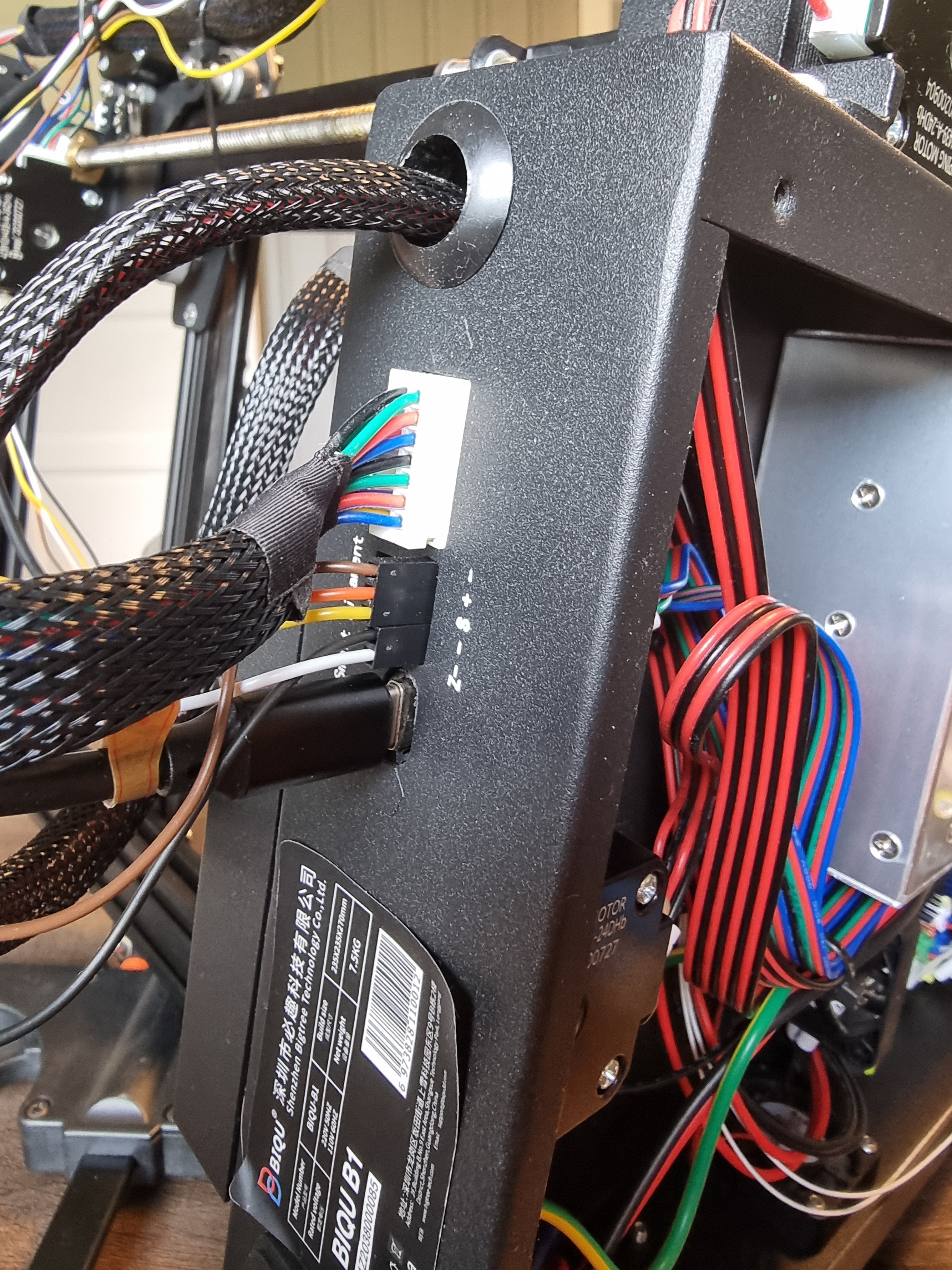
The Biqu B1 has all it’s wires to the hotend via a USB-C cable. All wires from the motherboard goes to a card in the back of the printer, and fom there is a USB-C to a card in the hotend. This card splits up to TH0, CNCFAN, CNCAN1, FAN2 and HE0. Even power to the nozzle heater goes in the USB-C.
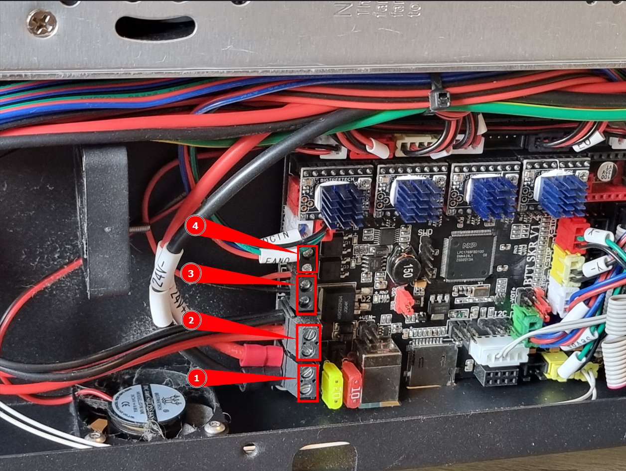
On the old SKR v1.4, the wire labeled DCIN were connected to FAN1 (GND - 12/24v), and FAN0 were connected to FAN0 (2.3 - 12/24v).
On the new SKR MINI V3 the DCIN wire is connected to FAN1 (12/24v - PC7), and FAN0 wire to FAN0 (12/24v - PC6).
The wire DCIN is not from PSU, but gives power to the card in the hotend.
In the printer.cfg all of fan-stuff are commented out, and the only thing is:
[fan_generic hotend_fan] #use for testing of hotend fan pin: PC7
pin: PC7

[fan] #part fan pin: PC6
Pin: PC6
This gives me sliders in Klipper for PC6 and PC7, and I can set FAN1 to 100%.
This should in (my) theory give power to the card in the hotend. But when i slide FAN0 in Klipper nothing happens with the fans.
When i disconnect the wires to the nozzle heater from the motherboard i now have about 24 volts on those wires, and this happens without heating the heater.
The reason for me starting this project was that one day i just got error message when heating the nozzle. First i bought a new heater, thermistor and the block they are mounted in. This did not help. So, now the motherboard is replaced and I’ve added a Raspberry PI with Klipper to the setup, and still no joy.


Thank you! This helped a lot.
Now, in the pinout for my old SKR v1.4 FAN0 is "12/24v" and "2.3", while FAN1 is "GND" and "12/24v".
What are the difference between FAN0 and FAN1 port on the motherboard?
(I’ve had a working 3D printer for 6 days, and have no experience with anything 3D printing related, so therefore these noob questions. )


Thanks. I’ve already used this one.
In the config file, some pins are named like “PB0”, but other have a “!” in front, like “!PB1”, and other a “^”, like “^PC2”. What are the “!” and “^” for?
What’s the difference between a “PB0” and a “PC11”.


Suspected that the SKR v1.4 original motherboard died (Hotend not heating), so advanced to the SKR MINI v3 + a Raspberry PI for Klipper.
I’m looking for “printer.cfg” that matches this setup…


Let me know if you have any questions>
I only have questions.
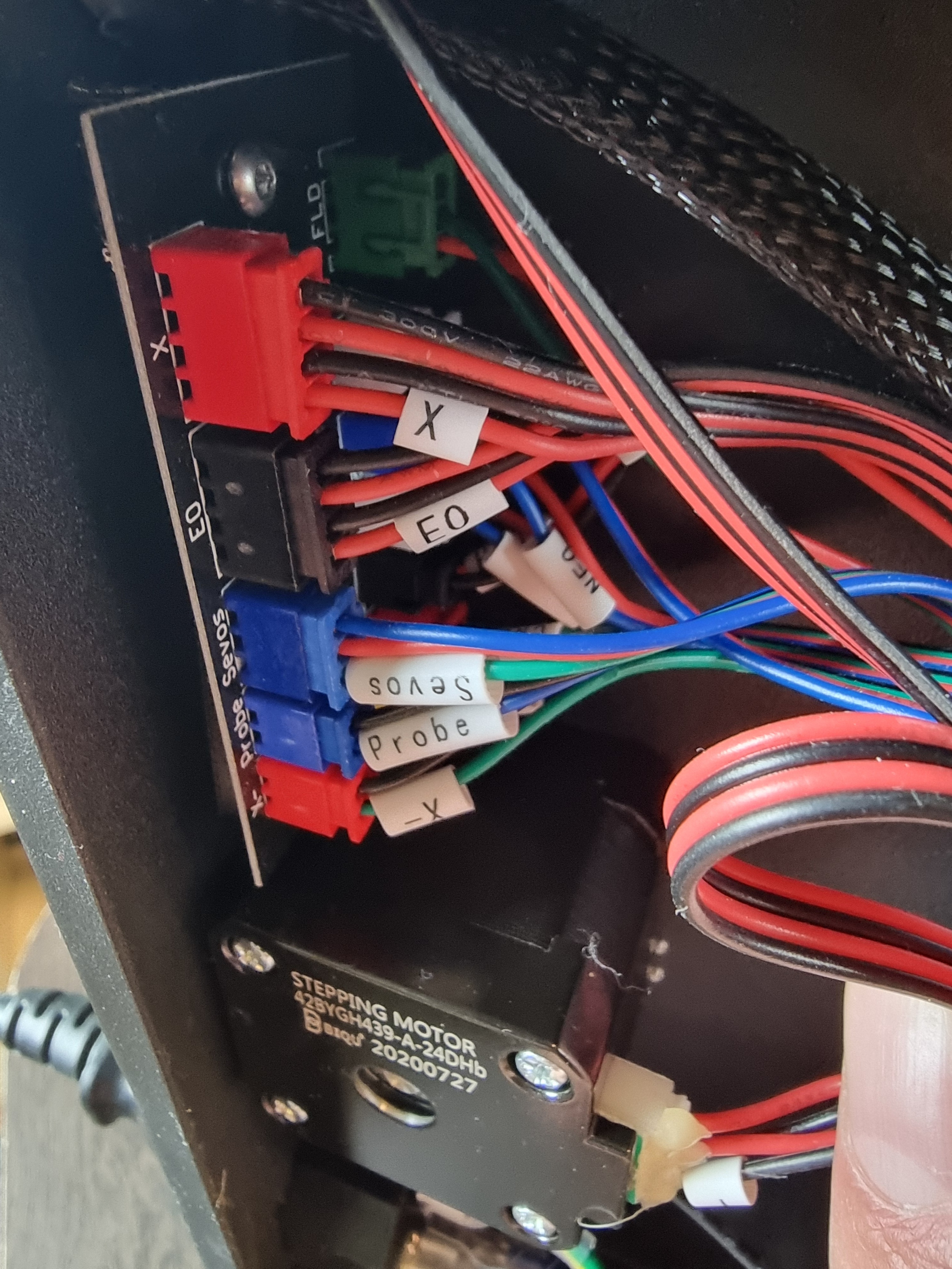
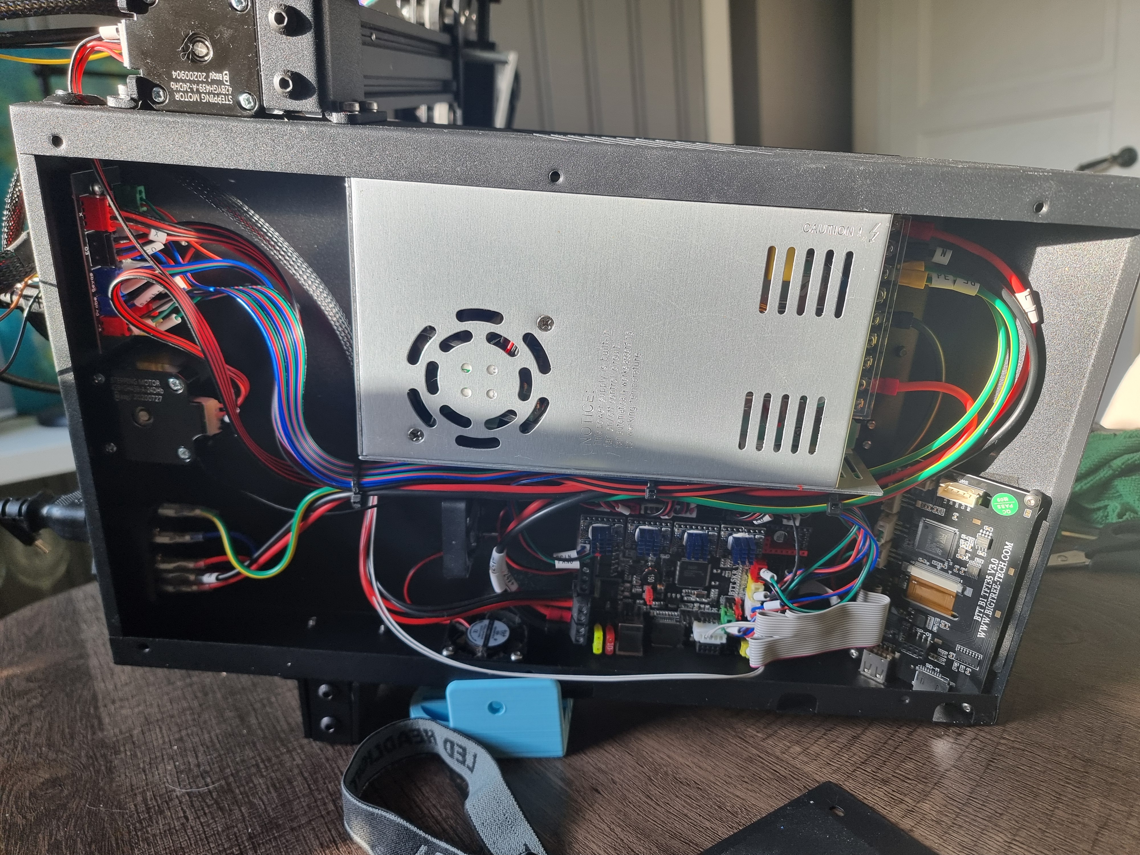
First things first, i probably should get control on the cables and their markings before i take out the old mainboard.
I’ll start this adventure as soon as the parts arrive. Parts are still in the mail somewhere…
Thanks for offering to help me out here.


SKR MINI V3 and a Rasperry Pi 4 (for Klipper) is ordered and in the mail…
Shit, what have i done. Haha


Yeah, it’s a pretty standard setup. The previous owner put a BLTouch on the printer but never got it to work. I’ve had the printer for about 2 weeks and was about to figure this ABL out, but it misses the ABL option in the menu.
I’m pretty new in the 3D print business and know nothing about flashing, compiling, and all the options you can do. You recommend the SKR MINI 3.0, and i didn’t know i could change the mobo to other than the original SKR V1.4. What are the benefits of changing to the SKR MINI? And, no, I’m not in the US. But I’ll find it here in Norway…
And Klipper? Not heard of that either, but a fast youtube peek tells me that this too might be interesting…


Yes, that little board connects many of the cables from the main board to one USB-C, the the black and the white connectors. The USB-C is the only one going to the hotend.
Anways, thank you, kind internet stranger, for trying to help me out with this. Looks like I’m gonna have to replace the mainboard.


Thanks for the links. Can’t see any scorching, and everything I’ve measured seems OK. If there are LED’s on the mainboard, i don’t know how to light them. As of now there are no lights on the motherboard, but everything beyond that heater works…


The thermistor temperature reacts to me touching the thermistor-end. This shows in the display- So i believe this is not the problem here…


The outside view


This is the board that has a USB-C on the outside for the hotend


#3 goes up to a board back on the printer. This board has multiple outlets, and one USB-C that goes up to the hotend.


Home, and done some measuring.
Old heater: 13,6 Ohm
New heater: 14,6 Ohm
So, no power to the nozzle heater. Now, how to verify the mosfet?


Nahh, just take parts out and lay every part side by side, and just put them back in reverse order… And, take some pictures underway of where all the connectors are connected. You can do this. Hell. i don’t know what I’m doing and I’m gonna at least try…


I will measure the voltage when I get back home later today. It probably will show no volts, so which board is defect? The little one in the hotend or the board on the other side of the USB-C cable? How to verify the mosfet?


Just need to verify which board needs to be replaced…


That sucks. I have no clue about 3D printers and did no research before buying this one used. Worked OK for about 6 days… Well 80 bucks…
Looking closer on the X, Y, Z and E ports i observe that the ports are labeled different on the two cards.
Old SKR v1.4: Square pin = 1B, next pin = 1A, next = 2A, and last is 2B. Also the order is EN | STOP | DIR
New SKR MINI: Square pin = 2B, next pin = 1B, next = 1A, and last is 2A. The order looks like EN | STOP | DIR
Should i rearrange the wires in the JST so that the wire that on the old card was connected to 1B, also is connected to 1B on the new card, and so on?
The EN | STOP | DIR part is in the same direction in the pinouts, even the whole connector is upside-down on the SKR MINI. Why is this? Is this just labeling the round pins?
Arrghh, I have so many noob questions…