

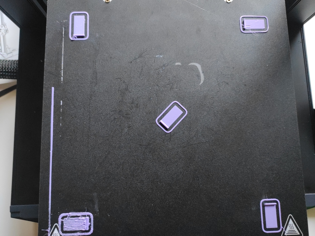
See attached photo for the results of the bed levelling test using superslicer’s calibration test.
This is using the uhhh mriscoc firmware after heating to thermal equilibrium, tramming to tolerance, doing a 9x9 mesh which found a high point at the super messed up bottom left corner (higher than tramming result? but slightly further out).
I have M420 S1 in my custom gcode, and for insanity’s sake checked the gcode of the part and it’s in the custom block and start block.
Any ideas what’s going on? every other section is okay, although back right is a bit distant.
EDIT 2023-07-11T08:27(UTC): So after some shenanigans the current findings are summarised as following:
- Z travel speed during probing needs to be slow
- multiple probing (3 samples) creates reproducible meshes and tramming wizard results
- Trying to enable the mesh via
G29 A ; Activate UBL \n G29 L0 ; Load mesh in slot 0 \n G29 J ; Correct for skewdidn’t seem to work. Replacing that whole block withM420 L0 S1makes the Z axis move during XY translation (from which I infer the mesh is loaded and being used correctly vs my printer is possessed) - The above would seem to me to indicate the marlin documentation is wrong? as it suggests using G29 L# and G29 A respectively.
As of the time of update, that lower right corner is proving troubling, still. I think it’s an issue with the location of the probe and interpolation results vs actual geometry of the bed. By that I mean, if we define down on your screen as positive X and right on your screen as positive Y the probe is located at MX, -NY vs the print head, thus the extreme location cannot be sampled. If the bed geometry is not smooth at that extreme then the automated fill in of my 9x9 grid might be wrong. I will attempt manually leveling that section and see if that helps
EDIT the second:
I’m going insane. Will take some photos in the morning but mesh values in the left front of the bed are wildly different from actual height.
Building the mesh with the probe will report a sort of hill in the centre going to low corners, the front left will report something like -0.3mm (although the mesh display only shows -0.2 mm editing the value shows it’s lower) but if I go into the edit mode and manually probe that location it’ll crash into the bed hard.
Setting it for light dragging on paper akin to the sort felt in the centre of the bed where values are accurate will have the mesh height at ~0.1 mm. A 0.3 mm difference? what the fuuuuuuuck?
EDIT: 2023-07-13T08+00:00: I figured it out. Thanks for your advice and patience. I will add pictures of the meshes at various stages to this post at a later date to assist any other wanderer in madness in identifying and solving the same problem.
In essence neither X or Y were square, the probe being offset in both X and Y created the problem. Because of the gantry construction it would be non trivial to square the XZ gantry to the Y axis so instead I verified that Y was not twisted and instead squared X to the best of my ability and precision tools.
Then I printed this part: https://www.printables.com/model/255096-sprite-extruder-ender-s1-pluspro-cr-touch-mount-fo to which my eternal gratitude goes out to a Mr S Grindset for providing in order to move the probe to be colinear with the print head in X. Ensuring that any error due to Y not being square is even for the probe and print head.
Now it is pretty good! Auto leveling works well enough to get “pretty even” layers, certainly none of the nasty ripples and ploughing I was experiencing.
hey, after finding the mesh did you send m500 to save the mesh?
Yes, the mesh saves and loads correctly. I had the Gcode wrong which you can see in my comment and the post edit. Ongoing issues though
So is it just g29 L0 that I need to add? I suspect mine is not using the mesh either
So all I have currently is
M420 L0 S1as I mention in my post. Make sure it comes after g28 in case that’s configured to unload autolevelling. Make sure L# matches the slot number your mesh is saved to.To see if it’s working. Print a skirt around the whole bed. Put an Allen key in the grub screws of the couples between the Z motors and the screws and watch or feel for deflection. The movements will be subtle.
It’s also worth seeing if comparing manual levelling using a feeler gauge or paper sheet and the nozzle tip creates the same mesh as automatic levelling using the probe. plus or minus Z offset of course. If there’s a skew to the manual mesh you need to fix axis alignment.